Welcome To Qingdao Novo Optoelectronics Technology Co., Ltd.
Whatsapp:+8613045000776


Cooled Thermal Modules
Keyword:
Introduction
Accesories
Recommended
1 Technical Specification
1.1 Detector
|
Detector |
MCT640×512 |
|
Spectral range |
3.7~4.8μm |
|
Pixel pitch |
15μm |
|
Cooling method |
Stirling Refrigerator |
|
F |
F4/F5.5 |
|
NETD |
≤25mk@25℃ |
|
Cooling time |
≤8 minutes in normal temperature |
1.2Function and Interface
|
Video output |
Standard PAL system for analog video signals |
|
Digital video |
LVDS |
|
Frame frequency |
25HZ |
|
Control communication |
RS232 or RS422 |
|
Correction |
manual correction/background correction |
|
Polarity control |
white hot/black hot switch |
|
Electronic Zoom |
×2/×4 electronic zoom |
|
Image enhancement |
Yes |
|
Cross display |
Yes |
|
Image turning |
Horizontal/vertical |
|
Power source |
DC 24 ~32 V, with power reverse polarity protection |
|
Power consumption |
≤15W@25℃, steady state |
1.3Command and Control
|
Operation Temperature |
-40℃~60℃ |
|
Storage Temperature |
-40℃~70℃ |
2 Physical size
|
Weight |
≤800g |
|
Sizes |
see details |

Figure1. Structural drawings
3 Core Electrical Interface Definition
Table 1. Connector (HARWIN:M80-5401605) pin definitions
|
Pin Number |
Definitions |
|
1,9 |
Power +, input |
|
2,10 |
Power -, input |
|
3 |
Video + output |
|
11 |
Video GND |
|
4 |
RS422_A |
|
12 |
RS422_B |
|
5 |
RS422_Z |
|
13 |
RS422_Y |
|
6 |
RS232_RX |
|
14 |
RS232_TX |
|
7 |
GND |
|
15 |
GND |
|
8 |
SER_LVDS_OUT- |
|
16 |
SER_LVDS_OUT+ |
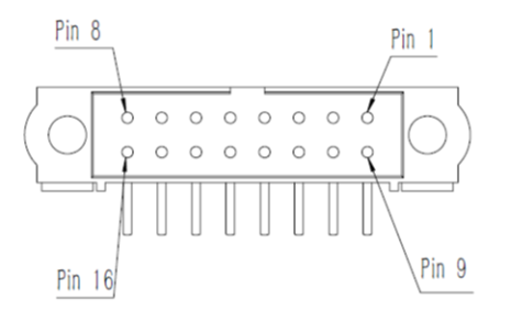
Figure3. M80-5401605 pin sequence diagram
4 Communication protocol
4.1 Electrical Interface Description for Communication Channel
Asynchronous serial communication is used between cooled thermal core and host computer, The hardware interface is RS232/RS422, Set up serial port hardware:
Baud rate: 19200 bps
Start bits 1 bit
Stop bits: 1 bit
Verification: None
Data bits: 8 bit
The parameters listed above may be different in practice, subject to requirement of the client.
4.2 Software Interface Description for Communication Protocol
a) The host controls the certain action of the thermal infrared core by sending commands to the thermal infrared core through the serial port; communication command is sent in given packet format; if the interval between characters of the packet sent from the host to the thermal infrared core is over 10ms, the imaging system may decline to implement the command.
b) Packet Protocol
Packet protocol is defined in Figure 4: Packet Protocol.
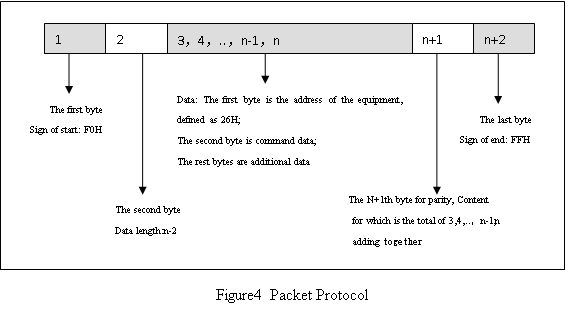
Table2. Communication data packet protocol explanation
|
Data packet protocol |
Explanation |
|
Start sign |
1 byte, hex value FOH |
|
Data length |
1 byte, X |
|
Data |
Data of X bytes |
|
Checksum |
low 8 bytes for the sum of X bytes |
|
End sign |
1 byte, hex value FFH |
|
Data Link Escape Character |
In the packet, if “FOH” emerges in data other than the signs of start and end, i.e. data between the second and N+1th, it should be changed to “F5H 00H”; |
|
Note data length |
Data length of the packet shall be determined by the number of effective data, and there is no need for bytes of the escape character to be added in. |
4.3 Communication Protocol Control Commands List
Communication protocol control commands list—pool of commands that can be sent from the host. See Table 3.
Table3 Communication Protocol Control Commands List
|
Name of Command |
Equipment Address |
Function Code |
Additional Data |
Notes |
|
Status Inquiry |
26H |
00H |
|
With feedback |
|
background correction |
26H |
02H |
|
|
|
manual correction |
26H |
03H |
|
|
|
Crosshair display |
26H |
04H |
1 byte. 00H is for crosshair hiding ; 0FH is for crosshair showing |
|
|
Polarity setting |
26H |
05H |
1 byte. 00H is for white hot; 0FH is for black hot |
|
|
Gamma adjustment |
26H |
06H |
1 byte, 1~23, default value is 8. |
|
|
Auto correction setting |
26H |
07H |
1 byte. 00H is for off; 0FH is for on |
Automatic manual correction, default setting off |
|
Electronic zoom setting |
26H |
08H |
1 byte. 00H is for off; 0FH is for on |
|
|
Video gain setting |
26H |
09H |
1 byte. 0~255. Default value is 128 |
|
|
Video brightness setting |
26H |
0AH |
1 byte. 0~255. Default value is 128 |
|
|
Crosshair X coordinate |
26H |
0BH |
2 bytes. 0~65535 from low to high |
|
|
Crosshair Y coordinate |
26H |
0CH |
2 bytes. 0~65535 from low to high |
|
|
Image enhancement |
26H |
0EH |
1 byte. 00H is for off; 0FH is for on |
|
|
DDE setting |
26H |
77H |
1 byte, 0~255. |
|
|
Focus position value setting |
26H |
18H |
3bytes,first byte is”12H” |
|
|
Zoom position value setting |
26H |
18H |
3bytes,first byte is”22H” |
|
|
Inquire Focus & zoom position value |
26H |
1DH |
1byte,00H |
|
|
Inquire max and min values of Focus & zoom position |
26H |
1DH |
1byte,20H |
|
|
Read accumulated working time |
26H |
1DH |
10H |
|
|
System reset |
26H |
80H |
|
Restore the default setting for parameters of the thermal core |
The commands listed above may be different in practice, subject to requirement of the client. The set ID is 26H, but it can be changed according to application environment.
4.4 Communication Protocol Feedback Commands List
Communication protocol feedback commands list – pool of the thermal infrared core feedback commands.
Instead of actively sending data, the thermal infrared core only responds when it receives “status inquiry” command. Its responding packet conforms to “communication packet protocol”.
Table4. Communication Protocol feedback commands list
|
Responding packet |
Equipment address |
Function Code |
Additional Data |
|
Status inquiry |
26H |
00H |
The first byte: |
|
Inquire Focus & zoom position value |
26H |
1DH |
The first byte:06H,cmd type |
|
Inquire max and min value of Focus & zoom position |
26H |
1DH |
The first byte:28H,cmd type |
|
Inqure working time |
26H |
1DH |
The first byte:16H |
The commands listed above may be different in practice, subject to requirement of the client. The set ID is 26H, but it can be changed according to application environment.
5 Digital video interfaces
LVDS transmission chip MAX9257 (use MAX9258 to receive). Definitions are in Table 5.
Table 5. LVDS signal list
|
MAX9257 |
Digital image definition |
|
Din0 |
Pxl_D0:image data,the 0th(the lowest) |
|
Din1 |
Pxl_D1:image data,the 1th |
|
Din2 |
Pxl_D2:image data,the 2nd |
|
Din3 |
Pxl_D3:image data,the 3rd |
|
Din4 |
Pxl_D4:image data,the 4th |
|
Din5 |
Pxl_D5:image data,the 5th |
|
Din6 |
Pxl_D6:image data,the 6th |
|
Din7 |
Pxl_D7:image data,the 7th |
|
Din8 |
Pxl_D8:image data,the 8th |
|
Din9 |
Pxl_D9:image data,the 9th |
|
Din10 |
Pxl_D10:image data,the 10th |
|
Din11 |
Pxl_D11:image data,the 11th |
|
Din12 |
Pxl_D12:image data,the 12th |
|
Din13 |
Pxl_D13:image data,the 13th(the highest) |
|
HSYNC |
HS:line synchronized and high efficient |
|
VSYNC |
FS:field synchronized and high efficient |
|
PCLK |
Pxl_Clk:pixel clock |
|
Others |
Reserved |
Data time sequence which is transmitted to MAX9257 transmission chip is showed in the following figure.
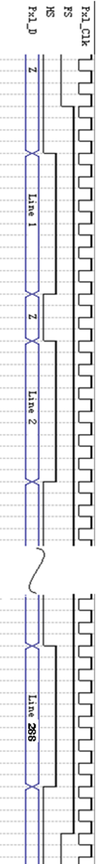
Figure 5. Data time sequence transmitted to MAX9257 transmission chip


信息为测试元素,使用时候可删除该元素放置自己想放的元素
这里是占位文字
信息为测试元素,使用时候可删除该元素放置自己想放的元素
CONTACT US
RELATED PRODUCTS
RELATED BROCHURES


We are a leading manufacturer of cooled and uncooled infrared thermal imaging camera and modules, surface or underwater fiber optic gyrocompass and inertial navigation system, fiber optic gyroscopes,etc.
Contact Us
Liando U Valley 25#, No.423, Juyang Rd, Huangdao District, Qingdao, 266425,China